Except for the fact that it doesn't contain a conventional power supply with transformer (and for this reason, I do not recommend this kit for beginners because of the electrical safety considerations), the circuit looks simple enough. Then I discovered that Velleman has another kit using the same microcontroller chip, but which has an entirely different function, the K8036 video signal cleaner. It's one of those black boxes that removes copy protection from DVD videos. You can also download the manual on that one. Here are two kits with completely different functions, yet they both use the same microcontroller chip, running a different program for the different application.
Reading the manuals on these two kits inspired me to read up on the PIC microcontroller chips. It made me wonder what else could be done with these chips, so I started the long strange trip of learning how to work with them. Although I was somewhat frustrated at first, it has definitely been a rewarding experience, especially after seeing my first program run on one of these chips. Unfortunately, it took almost all summer for that to happen, and hopefully, those who come after me will have an easier time, since you won't have to make the same mistakes.
Although writing programs for these chips is not the easiest task in the world (you have to know assembly language, and a lot of people don't have a head for that), I thought that I should get a PIC programmer and see what I could accomplish with these microcontroller chips. First, I had to find a book to learn how these chips work and how to program them, and the first one I became aware of was Programming and Customizing PICmicro Microcontrollers by Myke Predko. He even has a web site you can visit, but I don't think this is the best book to start with, or at least it wasn't for me.
Although the book comes with a circuit board for building a programmer, it's got too many problems (it is unclear on the direction to install a couple of transistors - seems that the same transistors from different manufacturers have different pin-outs (which is why a kit of parts with known pin-outs is always better than having to shop around for your own parts), and the circuit has been redesigned since the book was written, which you can see on the web site). Anyway I could never get the circuit to work, and rather than attempting to build some other programmer kit only to have it not work as well, I went ahead and ordered Microchip's PICSTART. Although it costs $200, I got tired of the hassle and wanted a programmer that would plug and play out of the box, and since it was made by the microcontroller chip manufacturer, I figured you couldn't go wrong.
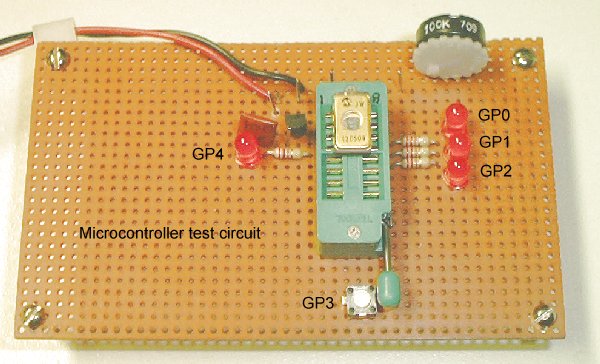
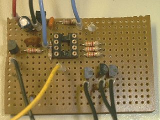
While I've been waiting for the programmer to arrive, I built a test circuit I can use to see if the programs I write are actually doing what I intend. Here's what it looks like.
The four light emitting diodes light when the output pins go high and are labeled. GP3 is a push button input. Once I program the chip, I can insert it into this board and see if the LEDs sequence properly. Once I get a lighting sequence the way I like it, I can finish building the actual lighting controller, which now looks like this:
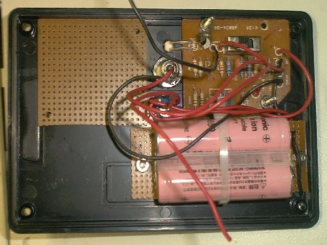
The blank circuit board (upper left) is where the microcontroller chip will go. The board will also contain four transistors to switch the lighting, a 5 Volt regulator for the microcontroller and a few other components. The circuit board that's already built is a solar controller that will turn the unit on at dusk, off at dawn and takes care of the battery charging from the solar panel. I designed this controller to operate in remote areas with no power. It will operate a string of 40 LEDs, 10 on each of the four circuits.
This is an ongoing project. I will add to this page once I get the programmer and start doing the testing. Now if I could only find some ultraviolet LEDs for my light strings. Below is a log of my progress.
 7-29-02:
The PICStart programmer came today and I had a little snag with it at first, but
after installing the software that came with it, it finally worked. I had the
MPLAB software already installed from Myke's book, but that didn't work with it
and I kept getting error messages. I had to install the new software over the
old, and that worked.
7-29-02:
The PICStart programmer came today and I had a little snag with it at first, but
after installing the software that came with it, it finally worked. I had the
MPLAB software already installed from Myke's book, but that didn't work with it
and I kept getting error messages. I had to install the new software over the
old, and that worked.
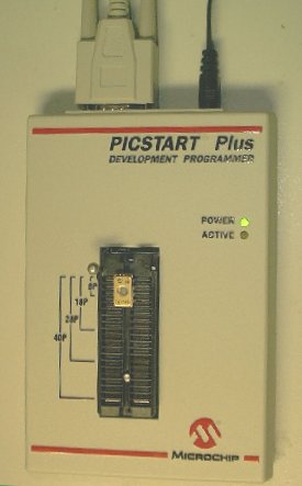
In the programmer's ZIF socket is a 12C509JW microcontroller. The JW means it is windowed and can be erased with an UV EPROM eraser. This is opposed to the one time programmable (OTP) that can only be programmed once. The erasable devices can be reprogrammed which makes them useful for testing. Then, once you get the program perfect, you can program the OTP devices, which are a lot cheaper than the windowed devices.
I was able to program my first device and verify it. But when I put it into my test circuit, it didn't work at all. The program (trainctl.asm) I used is from the CD-ROM out of Myke's book, so I assume my test circuit is bad rather than the program. Who knows how long it's going to take before I see some flashing LEDs.
8-1-02: Given the trouble not making the programmed chip function, I decided I needed an easier book, so I bought Easy Pick'n by David Benson and published by Square One, because that's exactly where I am right now, square one, actually maybe square two, since I was actually able to program the chip, just couldn't make it function. If I can get the experiments in the new book to work, that will be progress, but I think I need more hardware to do that.
Having a different book was much like having a second opinion. Each author has different ideas of ways to do things, and if the methods to do something in one book don't work, you can try some examples from another. I don't think I would have gotten very far with just one book, or even from several by the same author. So one piece of advice I have is get your information from several sources.
8-3-02: Ordered prototyping boards made by Micro Engineering Labs from Jameco, one of which is for experiments in the book. Once I get those built, hopefully I'll get better results. After reading Easy Pic'n, I feel I should design around the PIC 16F84 chips rather than the PIC 12C509 for the following reasons: Unlike the PIC 16F84, which has flash RAM that can easily be erased, the windowed PIC 12C509 chips are proving a bitch to erase without an expensive UV eraser. Leaving one out in the sun all day did not erase it. Never mind about all the fuss over the ozone layer, the sun doesn't seem to produce the right wavelength of ultraviolet light to do the job.
The second reason is the PIC 16F84 has 5 port A lines I can use as inputs and 8 port B lines I can use as outputs for lighting channels. I can use the five inputs for toggle switches for selecting the light sequences I want the chip to run. Five input lines gives you 32 items to choose from. The way this works is that each of the five inputs is treated as a binary digit (52=32. All inputs off = 0 and all inputs on = 31. Other combinations of on and off produce the other numbers. As a historical note, teletypes used to use a 5 bit code. That is why numbers had to be spelled out and STOP had to be used to indicate the end of each line, since there was no period).
8-7-02: Was not impressed with the prototype boards, or at least the lack of documentation that came with them. The main problem is knowing where to get the right parts for them, like the DIP header cable. I don't like the business of having to connect the prototyping board via cable to a breadboard or whatever. I think all the LEDs should be on the prototyping board for port B, plus connections for external switches for port A.
8-9-02: Got Pic'n Techniques book because it had information about the PIC 12C508, although that was only 18 pages of the book. Even so, I think I have a better understanding of how to program these chips if I can only find what I need to erase them. Once I overcome that problem, there may be a good chance I can make these chips do something.
I've been working on this project almost the whole summer and I would like to see some results. I'm also wondering if I'm even going to live long enough to obtain one of those Velleman kits that sparked my curiosity in the first place. They seem to be really slow getting them on the market. Maybe they're having trouble programming the dread PIC 12C508 also.
9-13-02: Success at last! It might be Friday the 13th, but I had some really good luck. First, the EPROM eraser came and I was able to erase the PIC 12C509 chip in about 2 minutes, when leaving it out in the sun for an hour hadn't worked at all. Using the information in Pic'n Techniques, I wrote a program to turn on and off each of the chip's four outputs, one after the other. Rather than try to print the program listing here, you can download iotest.asm and load it into MPLAB (or even Notepad, since it's a simple text file) to see how I did it. It's the first program I wrote that worked the first time, whereas the one I loaded in from the CD that came with Myke's book and programmed into a 12C509 didn't run at all. It was only after I got the ability to erase that program that I was able to program and test mine. It turned out his program was at fault, not my test circuit. Here's the test circuit doing it's thing. Now that's progress.
9-15-02: The next step of designing my lighting controller was modifying the program to use the external RC clock, so the light flashing speed could be controlled. This is adjusted with the 100K trimmer pot above the three LEDs on the prototype test board. That makes the program exactly simulate the Rainbow Kits CL-1 light chaser. The modifications to the program involved changing from internal clock to external RC clock, and changing the delay loop from 1 second to much faster, which involved changing two values.
The next step in program development involves writing more advanced lighting sequences. There also is the possibility of having a push button switch to change from one light pattern to another. Now that everything else is working, adding these improvements should be an easy matter. I'll probably end up with a better circuit than the Velleman kit before they even get it on the market. Their loss, my gain...
The software now works well enough to finish the actual lighting controller hardware. Once I got the software in the ballpark, I programmed an OTP chip for testing the hardware. Remember that lighting controller with the blank circuit board above? Well, it's about to be filled with parts. That makes me feel really excited. It won't be long before hippies can string flashing LEDs all over the woods, including ultraviolet LEDs.
It took an afternoon to build the first microcontroller circuit on the blank perf board. The circuit consists of a 78L05 voltage regulator, four transistors, six resistors, one pot to adjust the speed, three capacitors and the microcontroller chip. It proved much easier to build on a perf board than the Rainbow Kits circuit, since it only has one IC rather than two. When I tested it, it worked perfectly. Needless to say, I'm through using the Rainbow Kits circuit. It might have been great before there were any alternatives, but now there are. With just a little programming, I was able to produce a microcontroller chip that exactly simulates the Rainbow circuit, but the beauty is, that I'm not limited to that. I can write programs to do all sorts of lighting sequences that the Rainbow circuit could never do, since it is hard wired to do only the basic chaser function.
9-16-02: Like yesterday, I wrote software in the morning and worked on hardware in the afternoon. I wrote a light chaser program that would run a 1 of 4, a 2 of 4 and a 3 of 4 light chaser in both directions. I programmed each sequence to loop 32 times then move to the next. I'm pretty pleased with the results.
I did two mods to the hardware, added a push button switch to the controller I built yesterday to add a GP3 input, to allow lighting sequences to be changed at the push of a button. Now for a shot of the finished lighting controller circuit board:
The IC socket will hold the 12C509 microcontroller. In addition to the chip, the board contains a 5 Volt regulator, 4 transistors, 6 resistors, and 3 capacitors. Building the first one took about an afternoon. Now it goes much quicker.
To the test-prototyping board, I added 4 transistors and resistors, and a DIN connector to connect the light strings. I can also connect it to the triac switch to test line voltage lighting. This makes for a more flexible testing process now that I am no longer limited to watching the LEDs on the test board, now that I can connect it to the actual lighting circuits I plan to use it with.
9-17-02: Added subroutines to the program I wrote yesterday to set up the loop counter for various counts. I also added subroutines to output the 16 possible light patterns and to delay with one call to each subroutine. This should make the programs easier to work with and to modify. In addition, I added code to detect when a button connected to GP3 is pushed to switch from one lighting program to another. My controller units can now have a short lighting program aimed at conserving battery life (only one of the four LEDs is on at a given time), and a full featured lighting program for AC operation. Switching between the two is as easy as pushing a button on the controller.
10-16-02 The Velleman K8032 came and was a real disappointment, from both a hardware and software standpoint. In fact, except for the minor point that my version didn't include triacs or the zero crossing routine, it's function was identical to the second program I wrote for the PIC 12C509. In addition, they were so paranoid that someone would rip off their software, they code protected it so nobody could improve on it. The ironic thing about it is there was so little code to rip off.
Basically, the kit functions as a left to right, one of four light chaser, identical to the Rainbow Kits CL-1 circuit, except that it includes triacs to switch line voltage lighting. It contains four whole lighting patterns: light 1 on, light 2 on, light 3 on and light 4 on. Then it repeats. What a cop-out. The whole point of the microcontroller chips is you can write much more complex lighting sequences than that. But I noticed that the hardware has some real problems. It doesn't seem to be able to operate more than one light on at a time without problems. It may have been this problem that kept the product off the market for so long.
Before I go on, I think I should define some terms, so everyone will know what I'm talking about. A lighting pattern is the basic unit that defines which lights are on and which are off any given moment. In this case, it consists of four bits, one for each of the four lighting circuits. It is output to the output register, then a delay routine is called to insure that it stays visible long enough to be seen. With each instruction executing in a microsecond, you can see why the delay routine is necessary.
A lighting sequence on the other hand, consists of at least two or more lighting patterns, played in a given order and usually looped (repeated) several times. It might be helpful to think of each lighting pattern as punched into a punched card and for each lighting sequence to consist of a deck of punched cards. Each time a card is read, it turns on the corresponding lights. That's how it might have been done with computers in the olden days.
Finally, a lighting program consists of several related lighting sequences played one after the other as a group. Defined that way, the Velleman K8032 consists of one lighting program, consisting of one lighting sequence, consisting of four lighting patterns. With space for over 1,000 program instructions available, you can see how this is a waste.
I decided pretty near the beginning of programming the microcontroller chips, the usefulness of having more than one lighting program stored in a microcontroller chip. That would make it possible to have unique programs for special occasions, like for the Fourth of July or Halloween, that could be selected when needed. It could also mean that other programs could be written to conserve energy for battery power by limiting the number of lights on at any given time. The bottom line is that doing this allows one microcontroller chip to do the job of several. Now you probably have a better understanding of what I mean when I call the Velleman K8032 a real waste. It seems they spent much more effort in protecting the code than writing the program in the first place. That's where materialism and greed will get you.
To be continued, so stay tuned...
[return to the electronics index]
Copyright © 2002, Colin Pringle (colin@wild-bohemian.com)
The mail link automatically fills in the subject field so I will know which page
you're commenting on.
electronics/pic-cntrl.htm