Avon Blacklight modifications
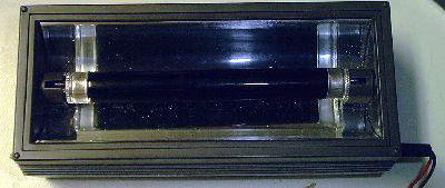
The following modification applies to the Avon Derma Spec Skin Imager
and the fluorescent driver board contained within. Both items can be obtained
from Electronic Goldmine as listed below. With a little work, you can build a
really nice portable ultraviolet light you can use out in the field.
-
complete
unit (G9589) in original packaging with 4-watt blacklight lamp and
12v @ 500ma wall wart power supply - about $1.95 - 7.95 (sometimes they have it
on sale).
-
Replacement 12 volt fluorescent
driver circuit board (G9614) from above - about $2 (see below for more
info.)
-
A better 6 volt fluorescent driver board that uses half the power and exactly
fits the derma-spec unit - about $4.00. You can get it with a white fluorescent
lamp (G13294)
or with a blacklight (G13250)
for a dollar more.
-
A miniature
toggle switch (G1944) to turn the unit on and off after completing
the mod (not needed if you use the above board).
If you can't find them there, here's another source at a slightly higher price.
Naturally, the complete unit is the better deal, especially if you want
a case and 12 volt wall wart power supply. The 12 volt replacement circuit
board might be useful if you want to practice the mod before doing it on
the complete unit (which is exactly what I did, since I had no idea how
the circuit worked at first) or for parts if your original unit should
stop working, but I prefer the new 6 Volt circuit board now being offered.
The 12 Volt unit runs for less than a minute and automatically turns itself
off, as do the 12 volt replacement boards. The purpose of the modification
is to allow the unit to run continually. The reason it doesn't is poor
design - it draws too much current in order to make the lamp operate a
little brighter. This causes the driver transistor (Q4) to run too hot
and also draws more current from the power supply than it was designed
to handle.
Since I first wrote this, the Electronics Goldmine is offering a newer
Derma-Spec driver board that runs on 6 volts rather than 12 and does not
shut off after one minute. If you can get this board, you can replace the
board in your Derma-Spec unit and have a unit more suited for battery power
(uses half the power) and without the annoying one minute turn off feature.
The back of the Derma-Spec unit even has a stash box big enough for 7.2
volt rechargeable lithium ion batteries (which will run the 6 Volt
driver board just fine) such as those sold by Electronics Goldmine (G4580).
I've tried this and it works great. The 1.1 amp hour batteries will run
the lamp for about two hours--not as great as most camping lanterns, but
a lot smaller, plus it can be charged by solar power in areas without electricity.
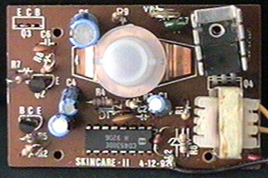
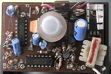
Below are two photos to help you identify the two driver boards.
 |
 |
|
The original 12 Volt board ( with Q3 removed for mod)
|
The newer 6 Volt board
|
The 12 Volt replacement boards I bought from Electronic Goldmine were minus
the white push button, but the newer six volt boards seem to come with
it. Since I have just gotten the newer board, I don't understand the circuit
operation as well as the 12 Volt board, only that it is a vast improvement.
I hope to figure a mod for the 6 Volt board to make it auto-start rather
than having to push the button, which would make it more useful for solar
lighting, where you want it to turn on at dusk and off at dawn. You are by no
means limited to using this unit as a blacklight. All you have to do is replace
the ultraviolet lamp with a white one.
All the Derma-Spec units I ordered had the older 12 volt boards, but
that doesn't mean there are not any 6 Volt units for sale. I just haven't
seen any. They may have discontinued the product before the 6 Volt units
were actually built and only have the circuit boards for them.
There are basically two options for upgrading your Derma-Spec unit,
modifying the existing 12 volt driver board as detailed below, or
replacing it with the 6 volt board, which in my opinion is the better option.
If you replace the driver board, you will also need you woll also need to
install a voltage regulator in the unit or get a 6 volt wall wart
or other power supply that can supply 500 mA, and will probably have to replace the
plug on it with a 5.5x2.5mm plug to fit the jack on the unit (more on this below).
In either case, you will probably want to tie the lamp socket contacts
together as mentioned below to prolong the life of the lamp.
The following modification to the 12 Volt board does the following:
-
Reduces power consumption of unit to no more than 500ma.
-
Disables the turn off after one minute circuitry.
Another modification you should make even if you replace the 12 volt board
with the 6 volt one is to install a jumper on the lamp sockets so the connection
goes to both pins at the end of the lamps as shown below.
To make the modification, you will need the following:
-
Soldiering iron and desoldiering tool.
-
Multimeter that can measure at least one amp of current (using a lower
range can blow the meter's fuse).
-
Small phillips screwdriver.
Now for the steps to make the modification for the 12 volt board:
-
Remove the door on the back of the unit and remove the four phillips screws
and stash them in a safe place. As a check to make sure your unit is the
same as mine, the circuit board says SKINCARE - II 4-12-92 on it.
The 6 volt driver boards has no markings like this.
-
You will need to hook a multimeter in series with the one of the power
leads to the circuit board. You may later want to run this broken connection
to a power switch (I unsoldiered the red lead from the circuit board, connected
a new one in it's place and when I was through making my measurements,
I connected a switch between the two and mounted it to the end of the unit.
The mod disables the push button on the unit and there's no easy way around
that.
-
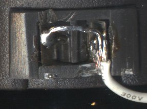
Each white lead from the circuit board needs to connect to both
contacts on each fluorescent lamp socket. As it comes, each only goes to
one of the two. Install a jumper between the two. That will prolong the
life of the filaments at the ends of the lamp.
-
Connect the positive test lead to the 10 amp jack on your multimeter. Failure
to do this could blow the fuse in it.
-
With the ammeter connected, turn on the unit and measure the current. As
it comes, this will be between 600 and 750ma. We need to adjust this to
500ma. Find VR1 on the driver board and use a small screwdriver to adjust
this counterclockwise until the unit draws 500ma, which is what the wall
wart is rated at.
-
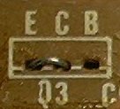
Remove the circuit board by removing the three phillips screws. Carefully
unsolder and remove Q3. You have to be careful not to damage the circuit
board traces when you remove it. Install a jumper between C and E where
the transistor was. That disables the auto turn off circuitry.
-
You may wish to add a on-off toggle switch at the end of the unit in the
line where you had the ammeter connected.

-
Reassemble the unit and you're done.
The lamp will operate a little dimmer now, but neither Q4 or the wall wart
will overheat. I left my unit on all night to make sure there were no overheating
problems and it passed the test. A 4-watt fluorescent lamp has a rated
life of 6000 hours and I have no idea how this mod affects that. Only time
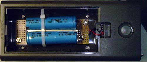
will tell.Adding rechargeable batteries to the unit: As I mentioned
above, there is enough room in the hidden compartment in the back of the unit to
add rechargeable lithium ion batteries, such as Goldmine (G4580).
After removing the batteries from the cell phone module, I mounted them on a
perf board and attached that to the unit with 4-40 bolts. I also added a switch
to disconnect the batteries when I wanted to run the unit on AC. Here is a
picture of the unit with the batteries installed.
A note about the wall wart connection: The plug on the wall wart
is a 5.5mm x 2.5mm power plug. You can probably find one of those at Radio
Shack (274-1569).
Now for a few notes about the circuit. Most of the circuitry is part
of the auto turn off feature, if you can call it a feature (I call it a
bummer myself.) This includes the MC 14538 IC, which is a monostable multivibrator.
I'm not sure why they used that IC rather than a 555 timer but it has the
same function. When you push the button on back of the unit, it turns the
unit on and starts the timer counting down. The output of the IC seems
to drive Q1 and Q2, which in turn drive Q3, which is the transistor that
switches the current on and off to the actual inverter circuit (and the
red LED under the button).
The inverter circuit is a transistor oscillator that converts the DC
current (supplied by the wall wart) to high frequency AC that the transformer
steps up to the high voltage needed by the fluorescent lamp. Since the intended application
(skin care) does not require battery power (it runs on a wall wart, which
requires line voltage), I'm not sure why the inverter circuit is used in
the first place, rather than a conventional fluorescent lamp ballast that
operates directly on the AC line voltage. Also, if they had spent the money
on the inverter circuit rather than on the auto turn off circuit, they
could have made it so it could handle the extra current without overheating
in the first place. Well, as the old saying goes, their loss, our gain.
Even in the olden days, a battery powered blacklight would set you back
at least $30 and required expensive 90 Volt or two 45 Volt batteries. With
a little work, the Avon unit makes a nice UV field unit or camping lantern
and is much brighter than those
UV
keychain LED lights that Electronics Goldmine had for $10 and the UV
pen lights that Edmond Scientific charges $150 for.
[return to the electronics index]
Copyright 2002, Colin Pringle
(colinp1@mindspring.com)
All rights reserved


