History: Although light chaser circuits have been around for over 100 years, probably first appearing in Times Square in New York, they used to require expensive noisy motor driven mechanical switches to flash the lights, so they were limited to commercial ventures that could afford them. By the 1970s, intergraded circuits and transistors eliminated the need for mechanical switches and dramatically reduced the cost of light chaser circuits so any hobbyist could build them. Light emitting diodes, which also became widely available in the 70s, reduced the power requirements of such circuits, making them even more affordable.
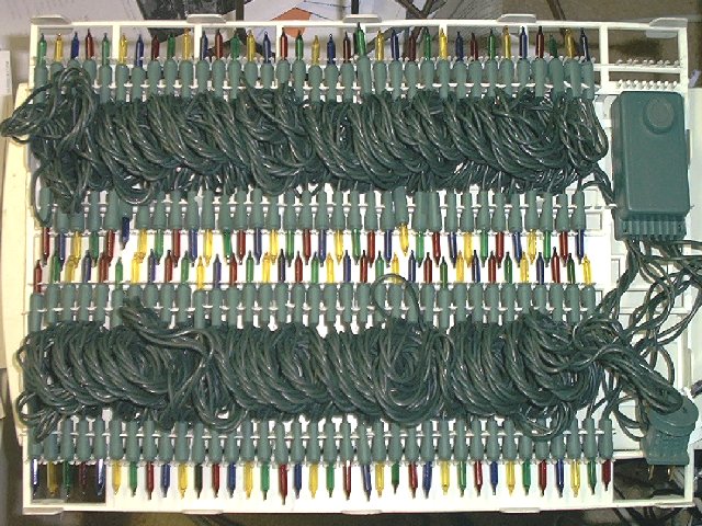
I'm not sure why light chaser circuits didn't become a fad in the 70s, which would seem like a natural thing to follow on the heels of the psychedelic era. As far as I know, no electronics kit company offered any such circuit to build until much later. The first I saw the light chaser circuits appear on the consumer market was in the form of Christmas lights in the late 1980s. This was a beautiful but short-lived fad because the strings didn't last very long. You can still buy these strings for about $8.00, probably the cheapest way to obtain a light chaser. Here is the latest such set I got (Christmas, 2002).
The green box at the right is the lighting controller, and I wouldn't be surprised if it contains a PIC microcontroller (more on that later). These strings usually contain 140 lights and are often called Motion Lights, or some variation on that theme. I bought this string to convert to an LED string.
Finally, in the late 1990s, Rainbow Kits offered a circuit (the CL-1) that could flash LEDs in the traditional light chaser fashion. Although not too colorful with the red LEDs provided, I built mine using red, yellow, green and blue LEDs, which looks as good as the ill-fated Christmas light chaser sets, but lasts much longer.
Another variation of chaser lights are the so-called rope lights. These are light strings contained in a tube, which makes them somewhat easier to handle. For those who don't like the idea of building a kit, these come assembled and ready to go, and cost a bit more. They come in two parts, the light string and the chase controller, each of which cost about $30. You can get them from Gem Sound and American DJ, among other places.
How they work: Light chasers consist of several lighting circuits strung together, usually three or four. Every first light in the string is turned on, then off and the next light is turned on and then off, and so on. Although there are eight lights in the example below, there are only four circuits controlling these lights, which are repeated twice. The two lights that are on at any given time are connected to the same circuit. In the Rainbow Kits light chaser, the four circuits can be repeated up to10 times, giving a string of 40 LEDs.

In the past, the circuit that controls the switching was usually a 1 in 10 counter, such as a 4017 IC. Each time this counter is clocked, one of the 10 outputs goes high, hence the name. Since usually only four of the outputs of the counter are needed to control the four lighting circuits, the fifth counter output was usually tied to the reset pin of the chip. When the chip reached the count of five, it would reset to one. The counter outputs drive transistors, which switches the load. The counter was clocked by an astable multivibrator, such as a 555 timer. There was usually an adjustment to control the speed.
Below is a picture of the Rainbow Kits circuit I built a couple of years ago (for Christmas, 2000) and mounted in a Radio Shack box.
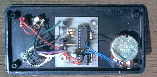
As you can see, the circuit consists of the two ICs, eight resistors, four transistors and one capacitor. I added a pot to control the speed, a power switch, power jack and a 5-pin DIN connector for the light string.
I now consider the Rainbow Kits circuit to be obsolete and no longer use it. Instead, I have designed a new lighting controller circuit based on the PIC 12C509 microcontroller chip made by Microchip. This is the same unit with the Rainbow circuit replaced with the microcontroller based circuit.
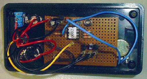
As you can see, the microcontroller chip (marked 0002) replaces both the 555 timer and the 4017 counter. The lower component count makes the circuit easier to build, especially when using a perf board. In this case, the microcontroller chip rather than a 4017 counter drive the output transistors. The most remarkable feature of the new circuit is that it is programmable. Rather than being limited to a hard wired simple left to right chaser, you can program any lighting pattern you can dream up into the microcontroller chip. I even added a push button to switch between lighting programs stored on the same chip.
To make the LED string, I cut apart an old Christmas miniature light string, leaving about 3 inches of wire on each socket. Each LED requires a series resistor depending on the voltage you use and the type of LED. I used 470 ohms for 12 volt operation. The string consists of five wires, a common wire that connects to one end of all the sockets and one wire for each of the four circuits.
The transistors on the circuit board are good for 10 LEDs @ 20 ma each (200 ma), and since there are 4 circuits, it can operate a 40 LED string with 10 LEDs per circuit. That consumes about 140 ma at 12 volts. That makes it practical to operate it on battery power for quite some time, making it ideal for areas without power.
The Rainbow Kits light chaser circuit, as well as the new one I have developed, can also be used to trigger strobes which have a remote input, such as those made by Gem Sound and American DJ. It can chase four strobes, each connected to one of the outputs. I recommend that you build a basic unit first before you tackle the fancy stuff though. The circuits are cheap enough that you can buy several. I built a basic unit first, then I decided what additional features I wanted and then built a more complicated unit.
Related articles:
[return to the electronics index]
Copyright © 2002, Colin Pringle (colin@wild-bohemian.com)
The mail link automatically fills in the subject field so I will know which page you're commenting on.
chr-info.htm