I hate to start this with a warning, but safety comes first. If you're new at electronics, please stick with the low voltage circuits, like the Rainbow Kits unit. There is no way you can be injured by a circuit like that even if you do make a mistake. The other kits are for advanced builders who already have an understanding of electrical safety and know the precautions that must be observed when working with line voltage equipment. Once you gain that experience, you should have no problem with building the line voltage kits. You can also buy line voltage devices that requires no assembly and are ready to use right out of the box, like the rope lights and other lighting equipment commonly sold in music stores and stage lighting companies. Now, with that little safety rap out of the way, let's take a look at some of the kits I have built, many of which came from Velleman.
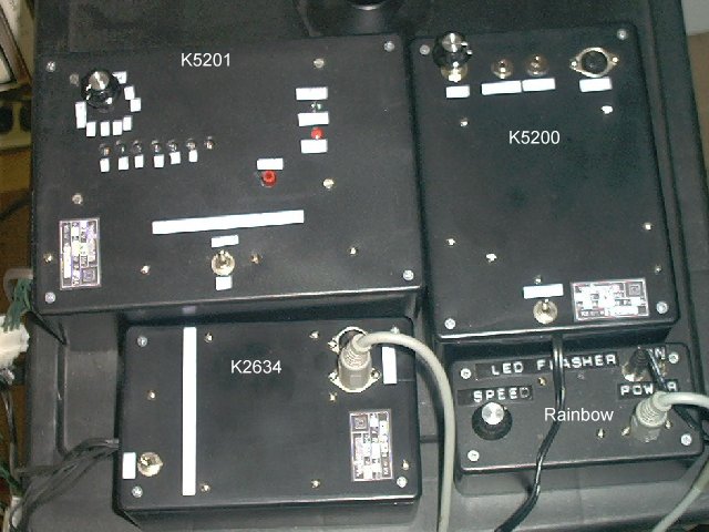
The first one I built was the K5201 light computer, which can control 7 channels of lighting. It is a fairly difficult kit to build and it took me over a year to find a box for it the right size. Building a 7-channel light string for this kit was also no trivial matter. Building one with 14 lights took all day and used up about 60 feet of Radio Shack wire. Since the circuit connects directly to the AC line, you have to be really careful when building the kit. It is probably possible to wire it for low voltage LED light strings, but I didn't configure it that way...yet.
If you go to the above link, you can download the manual and look at the circuit. Here's how it works. It uses a 555 timer to clock a counter which addresses an EPROM that has the lighting patterns stored it. 16 different lighting sequences are stored in this EPROM. There is a selector switch and bank switch to switch between these. The EPROM is 8-bit; 7 bits control the lighting circuits and the 8th is used as a flag to indicate the end of the lighting sequence (it resets the counter).
My biggest gripe with this kit is they don't provide any information about the EPROM or how to program it. It comes already programmed, with a sticker over the window. I would like to write my own lighting sequences. With 7 channels, there are many different patterns you can create. I should also mention that the hardware used in this circuit is pretty much obsolete, as the 555 timer, counter chip and EPROM can all be replaced with a single PIC microcontroller chip, with the lighting sequences stored inside. See the microcontroller page for more information on that. The kit costs $50 and probably will be much cheaper if they ever redesign it around a PIC microcontroller chip.
The second kit I built was the K5200 4-CHANNEL MULTI-FUNCTION RUNNING LIGHT. This is a much easier kit to build, and although it is intended to control line voltage lighting, you can leave out the triacs and build it to run low voltage LED light strings (which is exactly what I did). It has four modes that it loops through 32 times before switching to the next mode, flip flop, chase right, chase left and all lights on and off. It doesn't have any way to select these modes, they happen automatically. It is a little more interesting than just a light chaser that never changes modes, such as the Velleman K8032, but I consider this kit to also be obsolete.
Next, I built a K2634 quad triac switch card, which allows me to control line voltage lighting with a low voltage device, such as the Rainbow Kits circuit, or with my low voltage version of the K5200. The low voltage side is completely isolated from the line voltage side using opto-isolators. Since this is an interface device rather than a lighting controller, it's the only item on this page I don't have to worry about becoming obsolete.
The last kit I built was the K8032. I think they really skimped on this kit from both a hardware and a software standpoint. Instead of allowing the user to program their own lighting sequences, they give you a simple 1 of 4 chaser that is completely locked up (code protected). Ironically, at the same time they lock up the software, they give away the circuit diagram to anyone wishing to download it from their web site. That allowed me to design my own circuit and then test software on it long before I even obtained the actual kit. This is the only way to go if you want a circuit you can customize.
Finally, here's a look at some of the lighting kits I have built so for:
Notice that I use 5-pin DIN connectors to connect the low voltage light strings to the units or to connect the triac switch to control line voltage lighting. I use Molex connectors to connect the line voltage light strings to the triac switch and to the K5201. The output of the Rainbow Kits circuit is currently feeding the triac switch to control a string of 80 neon lamps. I have since upgraded the Rainbow circuit to a PIC microcontroller.
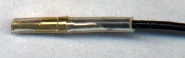
One note which should help when building the Velleman Kits is I discovered contacts that will fit the circiut board pins that are provided with the kits perfectly. This makes for super nice connections to the circuit board that can easily be changed. The female contacts are for sub-D connectors and can be found at better electronics stores. You can get about 100 of them for $5.00. I crimp them onto a wire and cover them with heat shrink tubing. Doing so makes the kits look that much more professionally built. You can find these contacts in the Allied catalog in the connectors section under Aim Electronics.

Here's what the socket looks like when crimped onto a wire and covered with 1/8th heat shrink tubing. It's now ready to push right onto the circuit board pin.
Copyright © 2002, Colin Pringle (colin@wild-bohemian.com)
The mail link automatically fills in the subject field so I will know which page
you're commenting on.
electronics/line-chs.htm